* Add layouts to rules.mk * Remove excess settings. Co-authored-by: Joel Challis <git@zvecr.com> Co-authored-by: Joel Challis <git@zvecr.com> |
||
|---|---|---|
| .. | ||
| keymaps/default | ||
| config.h | ||
| cradio.c | ||
| cradio.h | ||
| info.json | ||
| readme.md | ||
| rules.mk | ||
Cradio keyboards
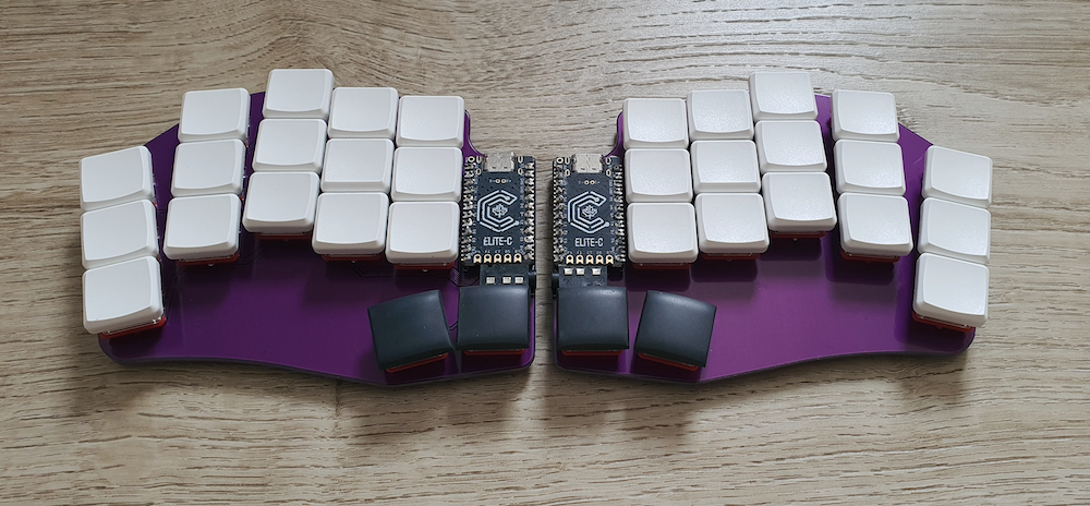
Cradio are minimalist 34-key split-keyboards designed with no diodes, using direct micro-controller pin wiring.
Keyboard Info
- Keyboard Maintainer: David Barr
- Hardware Supported:
- Cradio
- Sweep
- Hypergolic
- Variants of the same 34-key direct pin PCB
- Hardware Availability: order PCBs using gerber files from the repository
Make example for this keyboard (after setting up your build environment):
make cradio:default
See the build environment setup and the make instructions for more information. Brand new to QMK? Start with our Complete Newbs Guide.
Setting Handedness
Firmware uses handedness by EEPROM as default and it must be configured once on each side. The make commands are:
make cradio:default:dfu-split-left
make cradio:default:dfu-split-right
QMK Toolbox can also be used to set EEPROM handedness. Place the controller in bootloader mode and select menu option Tools -> EEPROM -> Set Left/Right Hand
Bootloader
Enter the bootloader in 3 ways:
- Bootmagic reset: Hold down the top left key on the left half (or the top right right key on the right half) and plug in the controller on that side.
- Physical reset button: Briefly press the reset button soldered on the PCB.
- Keycode in layout: Press the key mapped to
RESETif it is configured.
Swapped Pins
If you have one of the PCB variant with swapped letters Q and B / P and N, add the following code to your keymap's config.h to swap pins E6 and D7 in the firmware:
#undef DIRECT_PINS
#define DIRECT_PINS { \
    { D7, F7, F6, F5, F4 }, \
    { B1, B3, B2, B6, D3 }, \
    { D1, D0, D4, C6, E6 }, \
    { B4, B5, NO_PIN, NO_PIN, NO_PIN } \
}
#undef DIRECT_PINS_RIGHT
#define DIRECT_PINS_RIGHT { \
    { F4, F5, F6, F7, D7 }, \
    { D3, B6, B2, B3, B1 }, \
    { E6, C6, D4, D0, D1 }, \
    { B5, B4, NO_PIN, NO_PIN, NO_PIN } \
}
